
Breaking Down a Chiller Diagram: How Industrial Chillers Work
Industrial chillers are widely used to remove heat from processes and equipment. Chiller diagrams outline how these systems operate and show how refrigerant and process fluids move through the system.
This guide explains the main components of a chiller system and shows the differences between water-cooled and air-cooled designs.
Key Components of an Industrial Chiller System
Chillers are made up of several main components that work together to remove heat from process fluids and reject it to the environment.
- Evaporator: The evaporator is a heat exchanger where the process fluid transfers its heat to the refrigerant. Inside the evaporator, the refrigerant absorbs this heat and evaporates, initiating the cooling cycle.
- Compressor: The compressor draws in the low-pressure refrigerant vapor from the evaporator and compresses it into a high-pressure, high-temperature vapor. This prepares the refrigerant to release the absorbed heat in the condenser.
- Condenser: In the condenser, the high-pressure refrigerant vapor releases its heat to either water (in water-cooled systems) or air (in air-cooled systems), condensing back into a liquid state.
- Expansion Valve: This component precisely meters the flow of refrigerant into the evaporator, reducing its pressure and temperature to enable effective heat absorption in the next cycle.
- Refrigerant Loop: The closed-loop pathway that circulates the refrigerant throughout the chiller system, connecting all major components and ensuring continuous operation.
Additional Components:
- Pumps: Circulate process water or condenser water throughout the system, ensuring efficient heat exchange.
- Cooling Tower: Utilized in water-cooled systems, it removes heat from the condenser water loop by rejecting it to the atmosphere.
- Controls and Sensors: Monitor key system parameters and automate functions to maintain optimal performance and safety.
- Water Tank and Pump: Present in air-cooled systems, these manage the circulation of chilled water to and from the process.
- Refrigerant Reservoir and Dry Filter: Found in air-cooled systems, the reservoir stores excess chiller refrigerant, and the dry filter removes moisture and contaminants from the refrigerant stream.

Chiller System Process Overview
- Process fluid enters the evaporator, where heat is transferred to the refrigerant. This causes the refrigerant to evaporate into a low-pressure vapor.
- The refrigerant vapor is pulled into the compressor. The compressor raises both the pressure and temperature of the vapor, preparing it for heat rejection.
- The high-pressure, high-temperature refrigerant moves into the condenser. Heat is released either to the water loop (water-cooled systems) or to the ambient air (air-cooled systems). The refrigerant condenses back into a liquid during this step.
- The refrigerant passes through the expansion valve, which reduces its pressure and temperature, allowing it to return to the evaporator as a low-pressure liquid.
- The refrigerant, now in its low-pressure liquid state, is ready to absorb heat again in the evaporator.
- This cycle repeats continuously, providing stable process cooling as long as the chiller is operating.
Learn more about the chiller working principle here.
Water-Cooled vs Air-Cooled Chiller Diagrams
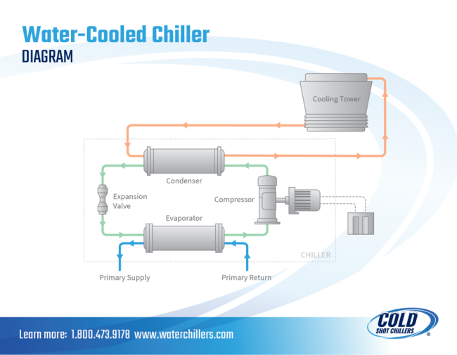
Water-Cooled Chiller Diagram
This diagram shows the flow of refrigerant and condenser water in a water-cooled chiller system. The condenser rejects heat to a dedicated water loop, which is then cooled by a cooling tower. This setup offers high efficiency in larger installations or facilities with existing cooling tower systems. Water-cooled chillers require additional components like pumps, cooling towers, and water treatment equipment, which can add to the installation and maintenance requirements.
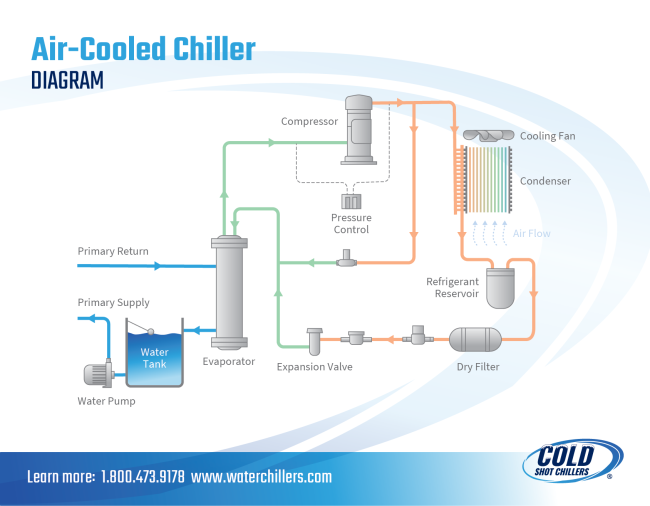
Air-Cooled Chiller Diagram
This diagram illustrates refrigerant flow and heat rejection directly to ambient air using fans that blow across condenser coils. Air-cooled chiller systems do not require a cooling tower or water loop, making them easier to install and maintain. These systems are often used in smaller facilities or where water access is limited. However, they can be less efficient than water-cooled systems in certain conditions, especially in high ambient temperatures.
Get More Support from Cold Shot Chillers
Chiller diagrams provide a clear view of how commercial chillers operate and how each component works within the system. Familiarity with these diagrams can support system operation, help with chiller troubleshooting, and assist in identifying issues more quickly. Even with these chiller diagrams, questions can still come up about specific setups, components, or operating conditions.
For more information or system-specific diagrams, contact the Cold Shot Chillers team.